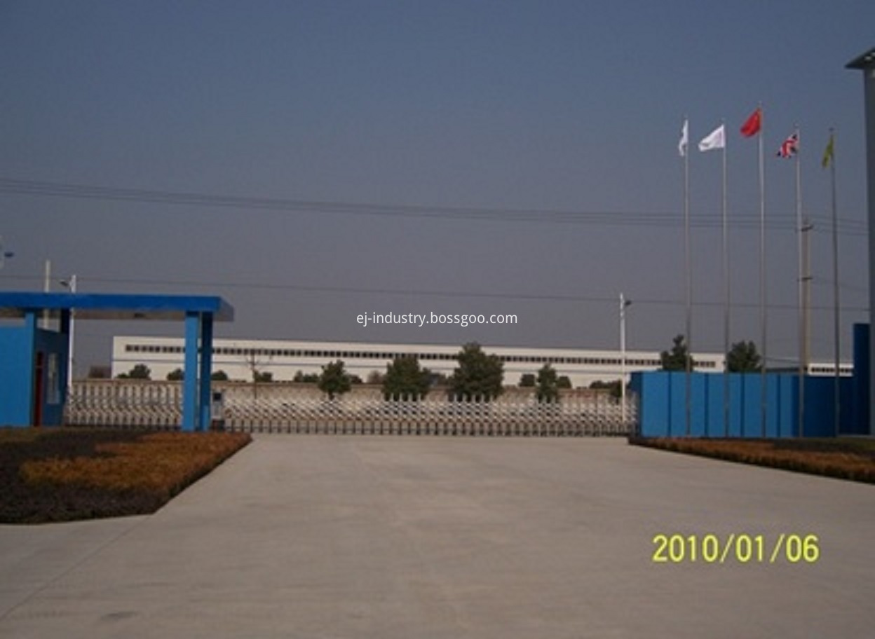
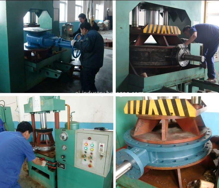
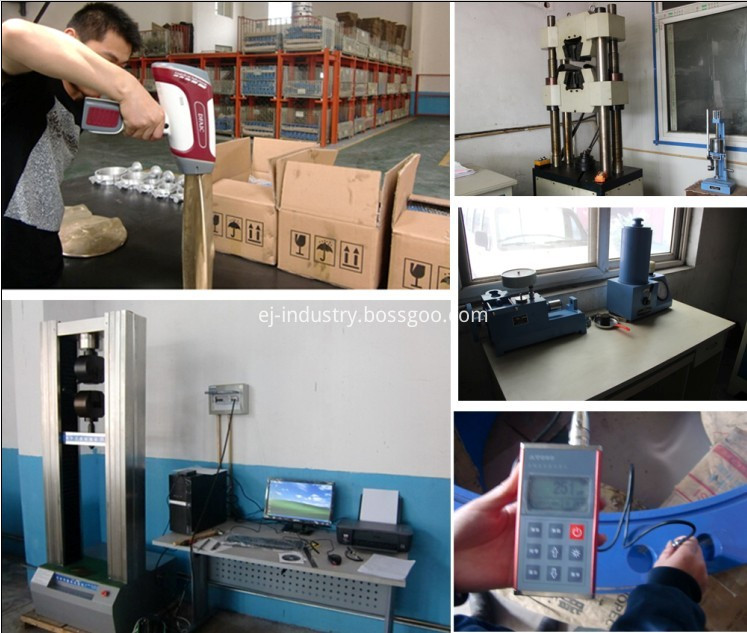
EJ industry is a professional manufacturer who specializes
in production for
low pressure cast iron and ductile iron valves.
The company has a total
investment of 7 million US Dollars and it is covering an
area of 44000 square meters. The area of building is 35000 square
meters. The company has a modernized production workshop and
production equipments, it's productivity is 12000 ton of valves per year.
The company has 300
stuff, among whom over 90 are technical college or above school record, 40 are intermediate above technical title stuff, and 120 are
senior technical staff in the company.
The company has the independent
research and development ability, and it also can carry on the
design and the production according to customer's request. The
company has over years experience in exporting valves. The main products
are BS 5163/ DIN3352 F4/F5 / AWWA C509 and socket end resilient gate
valve, BS750 Hydrant, BS5153(L/W) brass seal Swing Check Valve,
BS5163 brass seat Gate Valve, BS5152 brass seal cut-off valve,
Y-strainer, etc. Our products have been exported to Europe, American, Middle East,
Africa and Southeast Asia.
The company has been
certified with PED/CE, ISO9001:2008, and WRAS.
With remarkable quality,
competitive price and complete guarantees, the company win more and
more reputations in both domestic & international markets.
Welcome your customers from
worldwide to visit our factory and establish business with us!
Pneumatic Valve,Forging Steel Valve,Tilting Disc Valve,Plug Valve EJ INDUSTRY GROUP , http://www.ej-industry.com
Cao Qinglin's Model and Motion Analysis of a Three-DOF Planar Parallel Mechanism Used as a Planar Virtual Axis Machine Tool Cao Qinglin, Hong Xiaonan, Shen Shide (Nantong Institute of Technology, Nantong 226007) The solution of the inverse solution of a typical mechanism and the trajectory of its corresponding tool center.
Introduction The research on virtual axis machine tools is highly valued at home and abroad. The pseudo-axis machine tools are divided into space type and plane type. Among them, the mechanism for guiding the movement of the cutter head is a six-degree-of-freedom space parallel mechanism and a plane three-degree-of-freedom parallel mechanism.
The former can process complex three-dimensional surfaces, which can replace the ordinary CNC boring, milling, drilling and grinding machines to process plane trajectories. In general machining, boring, milling, drilling and grinding of plane trajectories are a common form of machining. In addition, the structure and control of planar virtual axis machine tools is simpler than that of space-based virtual axis machines, and the manufacturing cost is low. Therefore, the development of a planar virtual axis machine tool is more practical for general machining.
The most significant difference between a planar virtual axis machine tool and a conventional machine tool is that the former cutting tool is mounted on a planar moving member, and the member is a planar link mechanism connecting rod, which is called a planar virtual axis machine tool mechanism. Therefore, the primary task of studying the plane virtual axis machine tool is to select the appropriate linkage mechanism so that the movement track of a point on the connecting rod can meet the requirements of the cutting path. After the type of organization is determined, the organization is analyzed for motion. The main problem is to find the inverse of the institution. The solution of the type and inverse solution of the mechanism is the basis for the development of planar virtual axis machine tools.
1 The type selection of the mechanism is convenient for expression. The following is a milling machine as an example to illustrate the process of selecting the planar virtual axis machine mechanism. The traditional CNC milling machine drives the table by three servo motors to realize the movement in the x, y and z directions. The movement in the x and y directions determines the shape of the workpiece in the plane, as shown in Figure 1a. . Figure 1b is a schematic diagram of a planar virtual axis machine. The tool is mounted on the movable platform. The movable platform is the connecting rod of the three-degree-of-freedom planar linkage mechanism and is moved in a plane to ensure that the tool mounting point on the tool is required to move according to the trajectory requirement y = f (x). Therefore, the tool in the plane virtual axis machine tool not only rotates by itself, but also moves in the xy plane according to the cutting path requirement, thus replacing the movement of the table in the x, y direction of the traditional CNC milling machine. The movement in the z direction can be achieved by a direction-independent table or by the movement of the mechanism that drives the tool as a whole in the z-direction.
In actual cutting, the trajectory of the tool consists of several discrete points. In order to ensure the cutting accuracy, it is theoretically required that there should be an infinite number of discrete points coincident with the trajectory requirement y=f(x). Therefore, the problem can be attributed to the point-point guidance problem of infinitely precise points.
In general, the point guiding problem is realized by a link mechanism. Since the planar four-bar linkage (with a degree of freedom of 1) can only achieve precise guidance of a limited number of points, such mechanisms are not suitable. The plane five-bar linkage (with a degree of freedom of 2) can satisfy the precise guidance of infinite points, but after the two degrees of freedom satisfy the trajectory curve (x movement and y movement), it can not be used for other factors (such as the rotation law of the table). Or force condition) is preferred. A three-degree-of-freedom planar linkage mechanism can meet these requirements.
It is assumed that the three-degree-of-freedom planar link mechanism has one member, and the p low-numbered pairs have the =9, 12, and the corresponding mechanism is used as the plane virtual axis machine tool = 12 hours to form 7 and 98 different kinematic chains respectively. Mechanical Science and Technology Fund Project: Nantong City's 10 billion project funded project in 1999. Considering the mechanism as a plane virtual axis machine tool, some parallel motion chains with special structure can be selected. Figure 2 and Figure 3 are two types of mechanisms used as planar virtual axis machine tools and their corresponding kinematic chains. They are characterized in that the kinematic chain selected on the structure = 9 has two three sub-members, and the corresponding motion pairs of the two members. Connected between the II poles. When n= 10 and p = 12, the selected kinematic chain has two four-members, and the corresponding motion pairs of the two members are also connected by the II-stage rod group.
2 Inverse solution of the mechanism 2. Determination of the tool center trajectory The workpiece trajectory required to be machined is also called the actual trajectory. Cutting with a rotary tool of radius r, the trajectory of the tool center is called the tool center trajectory, as shown in Figure 4. The inner and outer contours of the workpiece correspond to the tool center N and point respectively.
The trajectory curve of the tool center N and point is now determined by the actual trajectory curve y= f( x).
In the coordinate system xoy, set the actual track y= any point A (x, y) on f(x), corresponding to the N point on the tool center trajectory. The three points are represented by vectors R and R, respectively, and h is the argument and magnitude of the vector R, respectively. Therefore, the vector R can be written into the formula, r is set to the derivative of the vector, and its argument angle is h A. The derivative of the equation (2) is derived and expanded to obtain the differential instead of the differential, that is, the vector of the dr is shun and counterclockwise. Turning 90° respectively, they will coincide with the vector sum, that is, the vectors A and AN can be written as r quantities R and R are combined and written as R, N, and the vector equations are used to represent the real and imaginary parts of the vector respectively. The equation can be obtained by inverting the Cartesian coordinate system xoy of the 2.2 mechanism, and the x-axis is parallel to the frame line A. Let the trajectory of the tool center point be y=( x). The positions of the three connecting rods are indicated by the angles T, U and V between the frame rod A B and the frame line A and respectively. The position of the member 7 is represented by the point coordinate (x, y) and the angle θ between the upper E line and the axis. The degree of freedom of the mechanism is 3, when the components 1, 3 and 5 are the active members, the movement of the member 7 is determined, and the positive solution of the mechanism is reversed, and the member 7 is taken as the active member, and the movement of the corresponding members 1, 3 and 5 is obtained. , that is, the values ​​of T, U, and V are the inverse solutions of the mechanism. The online real-time calculation of the virtual axis machine tool requires an inverse solution of the calculation mechanism, so the inverse solution of the mechanism is analyzed below.
Let the lengths of the members 1 to 6 be the distances from the three points to the tool center point, and the angles between D, F and E are θ and the coordinates of the θ point in the coordinate system xoy are respectively A. In the inverse solution of the mechanism, the member 7 is taken as the active member, that is, the point trajectory y=(x) and the corresponding rotation angle θ=θ(x, y) are motion inputs. Let Fig. 5 find the three points D on the member 7 (the coordinates of D are set to A, B, and the coordinates of the three points are (A) and respectively), and the coordinates of the A point for the components 1 and 2 are solved (A ), there are two solutions, which can be determined by the initial position of the organization. Similarly, for the members 3, 4 and the members 5, 6, the coordinate positions of the B point and the point can be obtained. The progress can be obtained by Cao Qinglin, etc.: The motion of the three-degree-of-freedom planar parallel mechanism used as the plane virtual axis machine tool and the motion analysis component 7 are y=(x) and θ= θ(x, y) are motion inputs, and can be used. (6) Find the coordinates of the points D, E, and F, and obtain the corresponding rotating members 7 of the members 1, 3, and 5 as the motion input members, and the motion trajectory of the points y=(x) is determined according to the contour of the workpiece to be processed. The angle θ = θ(x , y) can be selected as required. When selected, θ = 0, that is, the member 7 is translated, so that only the relative movement caused by the rotation of the cutter head itself is not between the cutter head and the workpiece, and there is no relative rotation caused by the rotation of the movable platform, which is advantageous for uniform cutting.
For the inner circular groove machined as shown in Fig. 6, the radius of the milling cutter r = 10. The obtained inverse solution results T, U, V are shown in Fig. 7.
3 Conclusion There are 7 kinds and 98 kinds of kinematic chain types for the three-degree-of-freedom plane eight-bar and ten-bar linkage mechanism. A structurally symmetrical mechanism of such a mechanism is typically employed as the mechanism for a planar virtual axis machine tool. Different types of mechanisms can be obtained by the transformation of different types of motion pairs, which makes it possible to have a greater choice when selecting a planar virtual axis machine mechanism.
Through the analysis of the inverse solution of the mechanism and the trajectory of the tool center, it provides a theoretical basis for the development of planar virtual axis machine tools.
[References] Huang Zhen et al. Parallel Robot Mechanism Theory and Control [ ]. Beijing: Mechanical Industry Press, 1997 Tsinghua University successfully developed virtual axis machine tools [ J]. World Science and Technology, 1998 Li Ying et al. Application Research and Development Trend of Virtual Axis Machine Tools [J]. Mechanical Design and Research [D]. Xi'an University of Technology, 1999 Mechanical Science and Technology


Type and Motion Analysis of a Three-DOF Planar Parallel Mechanism Used as a Planar Virtual Axis Machine Tool