The structure of the spiral concentrator is shown in Figure 38 . It is made by bending a chute into a spiral around a vertical axis. The spiral has 3 to 5 turns and is fixed on a vertical bracket. The spiral groove has a section of a parabola or an ellipse, and the bottom of the groove is in the longitudinal direction ( along the ore flow). Both the flow direction ) and the lateral direction ( radial direction ) have a certain inclination. Starting from the second ring, around the middle of the bottom product discharge pipe is provided with a weight (4 to 6), an upper discharge pipe with cross-sectional feeder, which can intercept heavy mineral ore into the exhaust stream so that the discharge pipe The two scrapers of the squeegee are pressed against the groove surface, and the movable squeegee therein can be rotated to adjust the opening angle between the two squeegees to adjust the discharge amount of heavy minerals, as shown in FIG. In order to improve the quality of the heavy product, a plurality of water adding points, called washing water, are provided at the inner edge of the tank, and the central water pipe is fed into the inner edge of the tank through the valve.
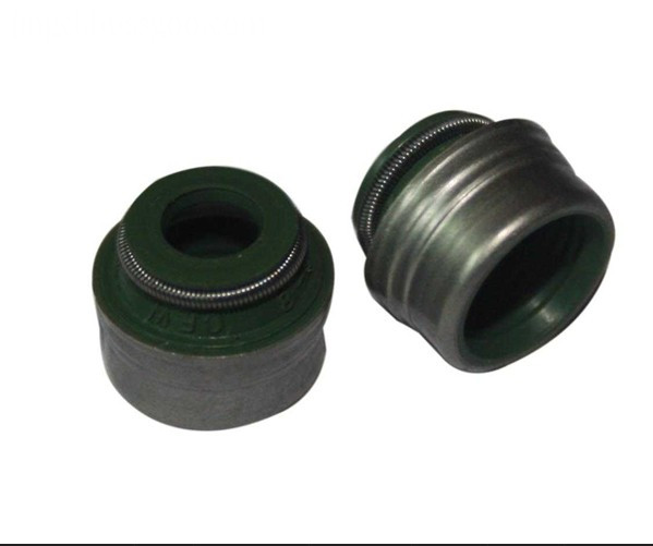
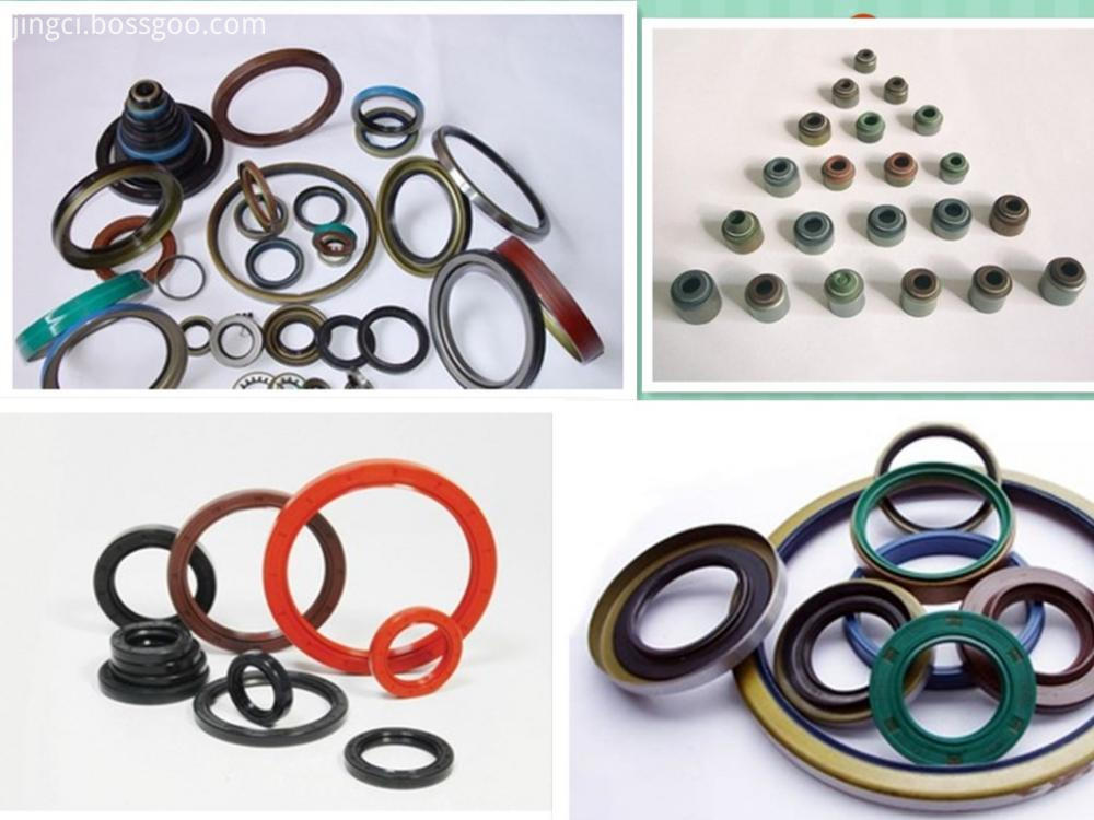
Oil Seal is used to seal oil (oil is the most common type of liquid substances in the transmission system, also refers to the general liquid substance) mechanical components, it will need lubricating parts and transmission parts output component segregation, unapt let lubricating oil leakage. Static seal and dynamic seal (general reciprocating movement) with the seals called seals. The representative form of oil seal is TC oil seal, which is a kind of double lip oil seal with self-tightening spring completely covered by rubber.
Oil seal of the scope of work related to the oil seal materials used: material is nitrile rubber (NBR) for - 40 ~ 120 ℃, Alec rubber (ACM) - 30 ~ 180 ℃, fluorine rubber (FPM) - 25 ~ 300 ℃.
Oil Seal Oil Seal,Rubber Oil Seal,Tamper Proof Oil Seal,Plastic Oil Seal Hebei Zhonghai Shipping Accessories Manufacturing Co., Ltd. , https://www.zhonghaiship.com


What is the structure and sorting process of the spiral concentrator?