Minimizes Costs- Maximizes Flexibility- Optimizes Distribution
√  3-speed centrifugal fan statically and dynamically balanced (for AC version)
√  EC Motor with modulating 0-5 V DC Input(for EC version)
√  Auxiliary Electric Heater Element for installation On-site or In-stock
√  Interchangeable left/right side coil connections
√  Auxiliary 1 row heating coil for installation On-site or in-stock
√  12,30 and 60 Pa External Static Pressure(ESP) models available (for AC version)
√  Variable External Static Pressures(ESP)up to 60 Pa(for EC version)
AC model + EC model
2 pipe fromÂ
Cooling: Â 1.7 kw ~ 9.9 kw
Heating: 2.04 kw ~11.7kw
4 pip from
(with heating coil)
Cooling: 1.7 kw ~ 9.9 kw
Heating:1.9 kw ~ 10.2 kw
Controller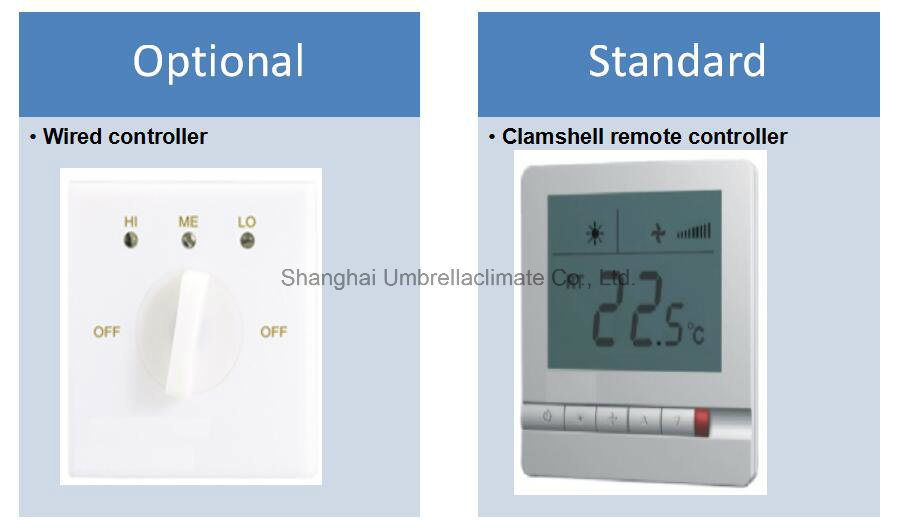
FCU Breakdown: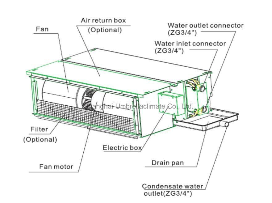
FCU Version: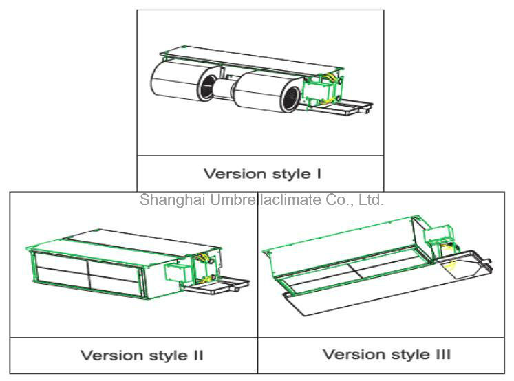
MULTIPLE FUNCTION: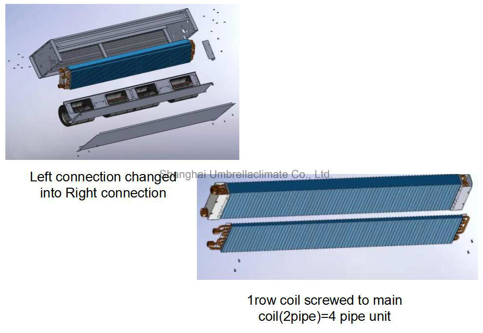
Production View: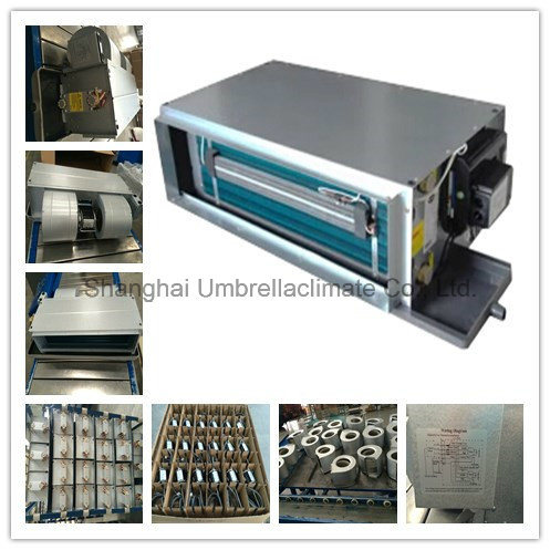
FCU Technical Data:
Â
Â
FC-WA(3R)-[Size]-V~
200
300
400
500
600
800
1000
1200
1400
1600
Unit Configuration
Configuration
2-pipe
Number Of Fan Blowers
Single
Twin
Three
Four
Three
Four
Power Supply
(V/Ph/Hz)
230Â /Â 1Â /Â 50
220Â /Â 1Â /Â 60
Operation Control
~S: Complete function onboard PCB with integrated group control functionality, incl. 1 pc return air sensor and 2 pcs temperature sensors.
~T: Terminal strip only.
Performance Data
Air
Air Flow
H
3
m3/hr
451Â
566Â
758Â
934Â
1179Â
1527Â
1754Â
1991Â
2586Â
2933Â
M
2
358Â
457Â
615Â
840Â
958Â
1220Â
1605Â
1871Â
2389Â
2666Â
L
1
278Â
293Â
433Â
571Â
779Â
896Â
1144Â
1573Â
2068Â
2482Â
Available pressure
H
3
Pa
75
75
75
75
75
75
75
75
75
75
M
2
75
75
75
75
75
75
75
75
75
75
L
1
75
75
75
75
75
75
75
75
75
75
Cooling
Cooling Capacity
H
3
Kw
2.43
3.08
3.9
4.8
5.99
8.01
8.72
9.87
12.8
14.6
M
2
2.02
2.59
3.3
4.42
5.09
6.7
8.14
9.4
12
13.5
L
1
1.65
1.8
2.5
3.24
4.32
5.23
6.23
8.2
10.7
12.8
Sensible Cooling Capacity
H
3
1.74
2.2
2.82
3.46
4.31
5.73
6.35
7.16
9.24
10.5
M
2
1.44
1.84
2.38
3.18
3.64
4.77
5.91
6.81
8.66
9.71
L
1
1.17
1.27
1.78
2.31
3.08
3.7
4.48
5.92
7.71
9.16
Heating
Heating Capacity
H
3
Kw
3.00Â
3.78Â
4.87Â
5.99Â
7.43Â
9.85Â
11.00Â
12.52Â
16.15Â
18.25Â
M
2
2.50Â
3.18Â
4.12Â
5.51Â
6.32Â
8.24Â
10.27Â
11.92Â
15.14Â
16.66Â
L
1
2.04
2.21
3.12
4.04
5.36
6.43
7.86
10.4
13.5
16
Max. Electric Heater Capacity@220V
1
1
3
3
3
3
3
3
3
3
Sound
Sound Pressure Level ( Outlet )
dB(A)
40/38/37
44/43/40
43/41/37
45/43/39
49/47/44
44/43/39
47/46/44
52/48/44
52/48/44
54/52/50
Sound Pressure Level ( Inlet + Radiated )
43/41/40
47/46/43
46/44/40
48/46/42
52/50/47
47/46/42
50/49/47
55/51/47
55/51/47
57/55/53
Sound Power Level ( Outlet )
49/47/46
53/52/49
52/50/46
55/53/48
58/56/51
53/52/48
57/56/53
61/57/54
61/57/53
63/61/60
Sound Power Level( Inlet + Radiated )Â
52/50/49
56/55/52
55/53/49
58/56/51
61/59/54
56/55/51
60/59/56
64/60/57
64/60/56
66/64/63
Electrical
Fan Motor Power
H
3
W
82Â
105Â
139Â
154Â
206Â
261Â
288Â
359Â
430Â
511Â
M
2
75Â
96Â
128Â
146Â
188Â
238Â
276Â
342Â
365Â
460Â
L
1
68Â
88Â
111Â
129Â
173Â
216Â
249Â
325Â
345Â
412Â
Fan Motor Running Current @ H
A
0.36Â
0.46Â
0.61Â
0.67Â
0.93Â
1.14Â
1.22Â
1.61Â
1.95Â
2.33Â
Fan Motor Starting Current @ H
A
1.08Â
1.14Â
1.35Â
1.95Â
2.10Â
2.70Â
3.52Â
4.81Â
5.65Â
6.75Â
Hydraulic
Cooling Water Flow Rate
3
L/h
417
528
669
827
1029
1375
1498
1694
2197
2501
2
347
445
567
758
873
1150
1397
1613
2064
2321
1
283
310
428
557
741
898
1069
1408
1842
2194
Cooling Pressure Drop
3
KPa
18.3
30.8
17
26.7
42.8
42.7
17.3
22.7
42.2
57.2
2
13.3
22.9
12.8
23.1
32.1
31.3
15.4
20.8
37.9
50.2
1
9.38
12.3
7.9
13.6
24.2
20.4
9.68
16.5
31.1
45.5
Heating Water Flow Rate
L/h
Same as "Cooling Water Flow Rate"
Heating Pressure Drop
3
KPa
14.75
24.82
13.7
21.6
35
24.8
14
18.6
34.7
47.4
2
10.72
18.45
10.3
18.7
26.3
25.5
12.5
17
31.2
41.6
1
7.56
9.91
6.36
11
19.8
16.6
7.85
13.5
25.6
37.7
water content
L
0.72Â
0.87Â
1.02Â
1.17Â
1.32Â
1.92Â
2.07Â
2.22Â
2.59Â
2.84Â
Construction and Packing Data
Water
Type
Socket(Threaded Female)
Connections
In
 mm [in]
3/4"
Â
Out
Condensate Drainage Connection
Dimensions
L
mm
755Â
855Â
955Â
1155Â
1255Â
1655Â
1755Â
1855Â
1755Â
1955Â
W
550Â
620Â
H
250Â
300Â
Net Weight
Kg
17Â
23Â
24Â
28Â
31Â
36Â
43Â
45Â
51Â
60Â
a. Cooling mode: Â Â Â Â Â Â Â Â Â Â Â Â Â Â Â Â Â Â Â Â Â Â Â Â Â Â Â Â Â Â Â Â Â Â Â Â Â Â Â Â Â Â b. Heating mode:Â Â Â Â Â Â Â Â Â
                       Â
- Return air temperature: 27C DB/ 19C WB.                         - Return air temperature: 20C.        Â
- Inlet/ outlet water temperature: 7C/ 12C.                          - Inlet water temperature: 50C.        Â
                                                        - Water flow-rate: same as cooling mode  Â
Â
Ceiling Concealed Fan Coil Unit (HVAC Terminal FCU)
Minimizes Costs- Maximizes Flexibility- Optimizes Distribution
√  3-speed centrifugal fan statically and dynamically balanced (for AC version)
√  EC Motor with modulating 0-5 V DC Input(for EC version)
√  Auxiliary Electric Heater Element for installation On-site or In-stock
√  Interchangeable left/right side coil connections
√  Auxiliary 1 row heating coil for installation On-site or in-stock
√  12,30 and 60 Pa External Static Pressure(ESP) models available (for AC version)
√  Variable External Static Pressures(ESP)up to 60 Pa(for EC version)
AC model + EC model
2 pipe fromÂ
Cooling: Â 1.7 kw ~ 9.9 kw
Heating: 2.04 kw ~11.7kw
4 pip from
(with heating coil)
Cooling: 1.7 kw ~ 9.9 kw
Heating:1.9 kw ~ 10.2 kw
Controller
FCU Breakdown:
FCU Version:
MULTIPLE FUNCTION:
Production View:
FCU Technical Data:
Fan Coil Chilled Water Air Conditioning Part
Model NO.: WA
Pipe: 2-Pipe Standard, 4-Pipe Optional
Coil: Hydrophilic Aluminum Fin
Electrical Heater: Available for Option
Thermostat & Valve: Available for Option
Filter: Nylon Filter
Trademark: U&C
Transport Package: Carton or Wooden
Origin: China
HS Code: 84159090
Model NO.: WA
Pipe: 2-Pipe Standard, 4-Pipe Optional
Coil: Hydrophilic Aluminum Fin
Electrical Heater: Available for Option
Thermostat & Valve: Available for Option
Filter: Nylon Filter
Trademark: U&C
Transport Package: Carton or Wooden
Origin: China
HS Code: 84159090
Ceiling Concealed Fan Coil Unit (HVAC Terminal FCU)